


What Is a Globe Valve and How Does It Regulate Flow?
Introduction
In industrial fluid systems, globe valves are among the most widely used devices for modulating flow and pressure. Their linear motion and relatively good controllability make them common in process control loops across chemical, oil & gas, power, water treatment, and evaporator systems. Meanwhile, MVR evaporators (Mechanical Vapor Recompression evaporators) have become increasingly favored in energy-efficient evaporation and concentration plants. In an MVR evaporator, precise control of flows (liquid feed, recirculation, vapor discharge, etc.) is critical - and globe valves often play key roles in those control circuits. In this article we will explore in depth what a globe valve is, how it regulates flow, and how it integrates into MVR evaporator systems (under process & control considerations).
What Is a Globe Valve? - Definition, Structure, Types
Definition and Basic Principle
A globe valve is a type of linear motion control valve used to regulate fluid flow through pipelines. The valve works by moving a disk or plug (attached to a stem) perpendicularly toward or away from a stationary seat, thereby modulating the flow cross-sectional area. The name "globe" originated historically when many such valves had spherical bodies, but modern designs may not be strictly spherical.
In process control terminology, the globe valve is often classified as a sliding-stem control valve (as opposed to rotary valves). According to the Control Valve Handbook, control valves (including globes) manipulate fluid flow by varying the size of the flow passage (i.e. the orifice) as directed by a control signal, thus controlling flow rate and downstream process variables (Emerson, Control Valve Handbook).
Skousen's Valve Handbook describes globe valves as one of the primary control valve types, especially suitable for throttling service due to their progressive flow control capability (Skousen, 1997).
From Industrial Process Control Valves (Arca/Artes), the focus is often on globe valves because of their reliable control behavior and relatively predictable flow characteristic in industrial loops (Arca/Artes, Process Control Valve Handbook).
Thus, the globe valve is both a structural and functional component: a valve body, internal parts, and a control mechanism (stem + actuator) that permits modulation.

Internal Structure and Components
A standard globe valve consists of the following key components (with terminology consistent with control-valve textbooks):
- Body / casing: The main pressure-containing shell; it houses the internal parts and connects to piping flanges or welds.
- Bonnet: The closure on the body that contains the stem packing and guides the stem. It is bolted or screwed to the body.
- Stem: A linear rod that drives motion of the plug/disc; it extends through the bonnet, sealed by packing, into the valve cavity.
- Plug / disc (or valve plugged element): The movable component attached to the stem; it moves toward or away from the seat to restrict flow.
- Seat ring / seat: The stationary surface against which the plug seals in closed position.
- Cage or guiding structure: Many modern globe valves include a cage or guide surrounding the plug to direct the flow, reduce turbulence, and define the flow characteristic.
- Packing and gland: Sealing around the stem to prevent leakage.
- Actuator / handwheel / operator mechanism: Manual handwheel in simple valves; pneumatic, hydraulic, or electric actuators in automated control valves.
- Accessories: Positioner, limit switches, volume boosters, snubbers, etc.
The plug typically moves in a straight line along the axis of the stem, passing through the cage or guide. The openings in the cage gradually expose more or less of the cross section as the plug moves, giving controlled modulation of flow.
A key internal design decision is the trim - the shape and arrangement of plug, seat, cage holes, and guiding structure - which defines the flow characteristic, linearity, and cavitation/noise behavior.
Types and Variants of Globe Valve
There are multiple variants of globe valves, designed for different services:
- Straight-through (in-line) globe valve - inlet and outlet are aligned (180° orientation).
- Angle globe valve - the flow path is bent, typically 90°, so inlet and outlet are perpendicular. This is useful where piping layout requires a change in direction or to drain the valve body.
- Y-pattern (or Y-globe) valve - the body is slanted (Y-shape) so that the stem is inclined and the flow path is less tortuous; this reduces pressure drop and wear.
- Balanced plug globe valve - the plug is drilled or bal anced to reduce net forces and improve controllability in high-pressure drops.
- Anti-cavitation or multi-stage trim globe valve - special internal trims designed to mitigate cavitation, noise, and erosion under high ΔP conditions.
- Cryogenic, high-temperature, or special material globe valves - variants for extreme service conditions.
Each variant has trade-offs in pressure drop, ease of control, cost, sealing, and maintenance.
Advantages and Disadvantages
Advantages of globe valves:
- Good throttling control: Because flow area changes gradually, they offer fine modulation capability.
- Predictable flow characteristic: Easier to model and tune control loops.
- Good sealing in shutoff: The plug-seat geometry can achieve tight shutoff.
- Robust against seat wear: The design is suitable for frequent operation.
- Flexible for retrofit: Many sizes and trims available.
- Lower noise and cavitation risk (relative to some rotary valves) thanks to better pressure recovery characteristics. (Globe valves have higher pressure recovery factors than rotary valves, meaning less energy recaptured, but this also means reduced risk of cavitation) (Baumann, Fluid Mechanics of Control Valves)
- Versatility: can be used for liquid, gas, steam, slurry, depending on materials.
Disadvantages:
- Higher pressure drop: Because flow path is not streamlined, there is more resistance.
- Larger size, heavier: Compared to ball or butterfly valves of same nominal size.
- Higher cost per unit flow (Cv) for large systems.
- Stem packing leakage risk over time.
- Maintenance more involved (especially for trims and seats).
- Sensitivity to flow-induced forces and potential instability in fast-changing flows.
Overall, designers choose globe valves where control precision is important and where the pressure drop is acceptable.
How Does a Globe Valve Regulate Flow? - Theory and Mechanism
To understand how a globe valve regulates flow, we examine the flow–characteristic relationship, pressure drop behavior, control accessories, dynamic forces, and stability phenomena.
Flow–Characteristic Relationship
A central concept in control valves is the flow characteristic - the relation between valve opening (stroke or plug lift) and flow rate (or flow coefficient). Common types are:
- Linear characteristic: flow is proportional to lift (i.e., doubling lift doubles flow).
- Equal-percentage characteristic: each increment of lift yields a proportional percentage change in flow (i.e., response increases at higher lift).
- Quick-opening characteristic: large increase in flow at small opening, then leveling off - useful for on/off or fast response.
The choice of characteristic depends on the process: for processes with wide dynamic range and non-linear behavior, equal-percentage is often preferred; linear is simpler and sometimes more intuitive.
Trim design (plug shape, cage holes) controls which characteristic the globe valve exhibits.
In operation, when the controller adjusts the valve opening, the plug moves, changing the exposed flow areas in the cage. The flow through the valve obeys orifice/flow equations, modulated by the valve's coefficient (Cv) which is dependent on lift and pressure differential.
Pressure Drop, Recovery Factor, Cavitation and Noise
A globe valve inherently introduces pressure drop. The pressure upstream (P₁) falls to a minimum at the vena contracta (lowest pressure), then recovers some static pressure downstream (P₂). The measure of how much pressure is "recovered" is captured by the pressure recovery factor (or recovery coefficient, often named F_L). Globe valves tend to have higher pressure recovery factors (i.e. less recovery) compared to butterfly or ball valves (Baumann, Fluid Mechanics of Control Valves) - meaning more of the pressure drop is permanent.
Because of this, the valve is less prone to cavitation (where vapor bubbles form and collapse) relative to certain rotary valves, but in high ΔP conditions cavitation still can occur if not mitigated.
Noise is another concern. High-velocity turbulent flow, rapid pressure drop, and cavitation can generate noise. Valve trims may incorporate noise-reduction or multistage drops (diffusers, cages, labyrinths) to mitigate noise.
Cavitation and flashing: If local pressure drops below vapor pressure, vapor bubbles form and collapse downstream (cavitation), potentially eroding the internal surfaces. If pressure stays below vapor pressure downstream, flashing occurs. To avoid these, valve designers use multistage pressure drop in controlled steps to lessen the per-stage ΔP (i.e., anti-cavitation trim).
In practice, the designer must ensure that the valve ΔP is within the safe range, and possibly add staging or bypass to protect the valve.
Actuation, Trim, and Control Accessories
A globe valve's plug motion is typically powered by an actuator (pneumatic diaphragm, piston, hydraulic, or electric motor). The actuator interprets a control signal (e.g., 4–20 mA or pneumatic 3–15 psi) to drive the stem position. To ensure accurate response, positioners, feedback, and accessories are used.
- Positioner: compares the command signal to actual stem position and corrects error (ensures precise movement).
- Limit switches, stroke stops: to define the end positions.
- Snubbers, volume boosters: to slow rapid movement or provide dynamic response.
- Supplies and control lines: for pneumatic or hydraulic systems.
The trim (plug + cage) is selected to provide the desired flow characteristic, pressure drop handling, and durability. In high ΔP or erosive services, multicavity trims, anti-noise trims, or staged flow reduction may be required.
Dynamic Forces, Flow-Force Compensation, and Stability
When fluid flows through a partially open valve, flow forces act on the plug, stem, and internal surfaces. These forces can destabilize the valve, cause vibration, or cause stickiness. Therefore, good valve design includes flow-force compensation where geometry or balancing holes reduce unbalanced forces.
A paper on flow forces in valves (Lugowski, Flow-Force Compensation in a Hydraulic Valve) critiques standard textbook formulae and proposes improved modeling of compensation based on pressure imbalances rather than simple Newtonian bucket models (Lugowski, 2015). Designers must be aware of these dynamic effects, especially at high velocities.
Valve stability is also affected by hysteresis, deadband, stiction, and backlash in the actuator-trim system. Positioners and calibration help mitigate these.
In summary: regulation is achieved by precise motion of the plug within a cage, and careful design ensures that the valve responds stably and predictably under flow forces, turbulence, and pressure changes.
Application in Process & Control Systems
Globe valves are not isolated hardware; their function is embedded in process control systems. Here we examine how they are used and designed in such settings.
Role of Control Valves in Process Control
In any continuous process plant, there are many control loops: variables such as temperature, pressure, flow rate, and level must be maintained around setpoints. The control valve is typically the final control element - the last device through which the controller's output (e.g. 4–20 mA) exerts influence. The controller calculates the desired valve opening based on measurements and error, and signals the actuator.
Specifically, for flow control, the valve adjusts the cross-sectional area to achieve the required flow given upstream/downstream pressure differences. For pressure control, sometimes the valve modulates flow to maintain downstream pressure.
Therefore, the designer must size and select the valve so that its controllability, rangeability, and response suit the dynamics of the process, without becoming the weak link of the control loop.
Sizing, Selection, and Tuning of Control Valves
Valve sizing involves calculating the flow coefficient Cv (or Kv in metric units) needed at full load, and ensuring the valve can operate effectively across the required range (e.g. from 10% to 100% flow). Key considerations:
- Rangeability / turndown: the ratio of maximum controllable flow to minimum controllable flow (often 50:1 or 100:1 in good design).
- Control authority: the fraction of the total system pressure drop assigned to the valve (often 30–70%) to allow modulation flexibility.
- Pressure drop (ΔP): allowable differential through the valve without causing cavitation or instability.
- Flow characteristic: linear, equal-percentage, etc.
- Dynamic response: the speed of the valve vs process dynamics.
- Operating conditions: temperature, pressure, fluid type, corrosiveness, presence of solids or dirty fluids.
- Materials and trims: compatibility, erosion resistance, life expectancy.
Once the valve is selected and installed, tuning the control loop (PID parameters) must consider the valve's dynamics, dead time, and nonlinearities. The valve should not introduce excessive lag or overshoot.
Integration of Globe Valves with Instrumentation
Integration means connecting the control valve to sensors, transmitters, controllers, and feedback devices. Some key points:
- A flow transmitter / flow meter measures actual flow and feeds it to the controller.
- The controller (DCS, PLC, PID algorithm) compares flow setpoint and measured flow, then outputs a control signal.
- The positioner / feedback system ensures the valve achieves the commanded position.
- Pressure or temperature sensors may be upstream or downstream of the valve to assist in derived loops (e.g. pressure compensation).
- Interlocks and safety logic must prevent valve misbehavior under abnormal conditions (e.g. fail-safe, emergency shutdown).
- Bypass and override valves may be used to protect the system or allow maintenance.
Thus, in system design, the globe valve is part of a chain: sensor → controller → actuator/valve → process. Each link must be reliable, accurate, and fast enough.
MVR Evaporator: Overview and Principles
To understand the role of globe valves in an MVR evaporator, we first review what an MVR evaporator is, how it works, and its system components.
What Is an MVR (Mechanical Vapor Recompression) Evaporator
An MVR evaporator is a system that uses mechanical recompression of vapor to recycle energy in evaporation processes, thereby increasing thermal efficiency. Instead of using fresh steam to heat the feed, an MVR system takes a vapor produced by partial evaporation, compresses it (raising its pressure and temperature), and uses it as the heating medium for further evaporation. This loop reduces external steam consumption and boosts energy efficiency.
As described in "MVR (Mechanical Vapour Recompression) Systems for Evaporation, Distillation and Drying," MVR systems reuse energy that would otherwise be lost, making evaporation more efficient. (Technical Information Document, 2019)
Because of this, MVR evaporators are used in industries aiming to minimize energy usage, e.g. wastewater concentration, chemical solutions, biomass, dairy, etc. (Myande, The Ultimate Guide to MVR Evaporators).
Thermodynamic and Energy Advantage
In traditional multi-effect evaporators, steam is used in successive effects; in contrast, MVR raises vapor to higher enthalpy mechanically, requiring only electric power for compressor or blower. This often results in much lower energy consumption. According to the MVR technical information document, the energy savings can be significant because the system recycles latent heat internally (Technical Information Document, 2019).
The specific energy consumption (in e.g. kWh per tonne of water evaporated) is often lower in MVR than in conventional steam-driven systems. The capital cost is higher, but overall lifecycle economics often favor MVR, especially when energy prices are high.
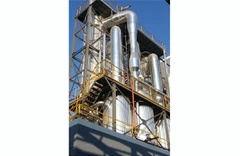
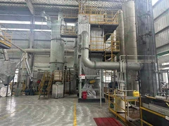
Typical Layout and Major Equipment
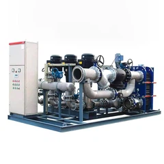
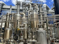
A typical MVR evaporator system includes:
- Feed pump: to supply liquid feed to the evaporator at a required pressure.
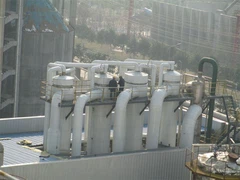
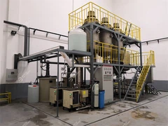
- Heat exchanger / evaporator body: where the liquid is heated and vapor is generated.
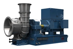
- Compressor / blower: to elevate the vapor pressure and temperature.
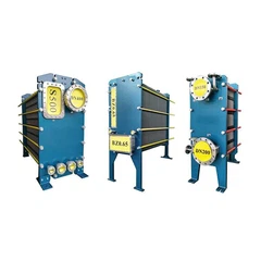
- Condenser or reboiler heat transfer surface: where compressed vapor condenses and transfers heat to the feed side.
- Recirculation pump / loop (in forced circulation systems).
- Separator / flash drum: to separate vapor and liquid phases.
- Control valves and piping: for feed, recirculation, vapor discharge, bypass, and drains.
- Instrumentation: sensors for flow, pressure, temperature, level, conductivity, etc.
- Safety devices: relief valves, vent valves, check valves.
The process flow is typically: feed enters → partial evaporation → vapor is compressed → compressed vapor condenses in exchanger → latent heat drives evaporation → vapor is separated and recirbed or discharged → concentrated liquid is withdrawn.
Because of the closed loop of vapor, control must manage pressures, mass balances, and flows carefully.

The Role of Globe Valve in an MVR Evaporator (Process & Control)
Now we merge the two themes: the globe valve and MVR evaporator, focusing on how globe valves operate within MVR systems under process & control logic.
Where a Globe Valve Is Used in an MVR System
Within an MVR evaporator system, globe valves may be placed in several strategic locations:
- Feed flow control: regulating the liquid feed into the evaporator body.
- Recirculation control: in forced circulation systems, controlling circulation pump or loop flows.
- Vapor bypass or throttling: controlling vapor flow or bypass during startup, part-load, or safety events.
- Liquid drawdown: controlling the concentration draw-off line.
- Vent or bleed control: to remove non-condensable gases or maintain vacuum.
- Makeup water or auxiliary stream control.
Because these points often require modulation (not just open/close), globe valves are natural candidates.
Functions: Regulation, Isolation, Bypass, Control Loops
Let us consider a few key loops and how globe valves function:
- Feed control loop: The feed flow must match evaporation capacity. A globe valve (feed control valve) receives a setpoint (e.g. desired mass flow), and adjusts its plug to maintain that flow against varying upstream pressure or fluid density changes.
- Recirculation control loop: In forced circulation systems, recirculation rate greatly affects heat transfer and fouling. A recirculation globe valve modulates the loop flow.
- Vapor throttling / bypass: During transient or startup phases, too much vapor pressure may build; a globe valve may throttle or bypass vapor to maintain stable pressure or protect compressor.
- Draw concentration control: The valve controls the outflow of concentrated liquid so that the liquid level or concentration remains steady.
Each of these loops is a process & control loop: sensors measure flow, pressure, temperature, or level; controllers determine actuation; and the globe valve executes the modulations.
During design, one may create cascade loops or feedforward/feedback control where the feed valve is subordinate to a pressure or temperature loop. The valve must have enough authority and dynamic response to maintain stability.
Control Strategies: Feed Flow, Vapor Flow, Pressure, Level
Let us examine a few control strategies:
- Feed–vapor balance: Because mass conservation must hold, feed flow and vapor flow must be matched. A cascade control scheme may regulate vapor pressure, and the feed globe valve operates under vapor pressure loop commands.
- Pressure control: The vapor pressure inside the evaporator influences boiling and heat transfer. A vapor throttling globe valve may be part of a pressure loop to maintain pressure at setpoint.
- Level control: The liquid inventory inside the evaporator must be controlled. A drawdown globe valve ensures constant level; if concentration varies, this loop must adapt.
- Recirculation loop control: The recirculation globe valve may be controlled to maintain a minimum velocity or heat transfer coefficient.
Because multiple loops may interact (e.g. feed loop interacts with pressure loop), careful tuning and decoupling strategies are required. The valve dynamics (dead time, lag, nonlinearity) influence how aggressively the controller can act.
Interaction with Other Devices (Pumps, Compressors, Heat Exchangers)
Globe valves in MVR systems must work in concert with pumps, compressors, and heat exchangers:
- Pumps: The feed or recirculation pump must supply enough pressure head; the valve must be sized so that the pump–valve system falls within a controllable operating region (not too near shutdown or surging). The valve must not push the pump into unstable region.
- Compressor / blower: When throttling vapor, the valve must not cause upstream instabilities (surge) in the compressor. Coordination of valve and compressor control is critical.
- Heat exchanger load: The amount of compressed vapor condensed must match the evaporator duty. The control valves modulate flows so that heat transfer remains stable; if fouling changes, control loops adapt via valve adjustments.
- Recycle or bypass lines: To protect the system or during startup/shutdown, bypass lines with globe valves allow alternate paths or limit flows.
In sum, the globe valve is a modulation tool within an integrated system. Its design, response, and control must be seen in context of all devices in MVR.
Comparative Discussion: Other Valve Types and Devices in MVR Systems
While globe valves are common, alternative valve types and devices have roles too. It is instructive to compare them.
Ball, Butterfly, and Plug Valves - Trade-offs
Ball valve: often used for on/off service. They offer low pressure drop when fully open, rapid actuation, and tight sealing. However, their flow control precision is poorer than a globe valve (the "ball" geometry leads to a less linear control characteristic) (Wikipedia, Ball Valve).
Butterfly valve: suitable for large pipe sizes and low cost, but flow control is less precise, and pressure drop and turbulence may be higher due to the disc in flow path (Wikipedia, Butterfly Valve).
Plug valve: used sometimes in control applications, but generally less favored for fine modulation.
When precise regulation is needed (as in feed, vapor control in MVR systems), globe valves remain preferred despite higher cost and drop.
Check Valves, Safety Valves, Relief Valves
In MVR evaporator loops, one also sees:
- Check valves: prevent backflow, e.g. vapor or liquid reverse flow. Must be sized to minimize pressure drop but also respond quickly.
- Safety relief valves: protect against overpressure in vapor circuits; typically spring-loaded and set to open beyond design pressure.
- Pressure relief / blowdown valves: for emergency discharge of vapor or gases.
These valves are seldom modulating - they are protective devices - but their presence and close coordination with the control valves are essential for safety and stability.
Heat Exchanger Control Duties vs Valve Duties
In the MVR system, heat exchangers perform duty by condensing compressed vapor and transferring heat to the feed. The valves regulate the mass and energy flows. A misbalanced valve action can lead to mismatches in heat transfer, fouling, or operational trouble. Thus, valve design must consider how heat exchanger loads vary over time, fouling changes, and transient response.
Pumps, Compressors, Recirculation Devices
As earlier noted, pumps and compressors are active devices and their operational curves must match the valve's range and dynamics. Recirculation devices (e.g. recirculation pumps, bypass loops) may alleviate the load on valves by offering alternate paths or managing extremes.

Practical Considerations, Challenges, and Best Practices
Designing and operating globe valves in MVR systems (or other process systems) brings many practical challenges. Below are best practices and cautionary points.
Material Compatibility, Erosion, Corrosion
The fluids in evaporators may be corrosive, contain solids, or have fouling potential. Valve bodies, plug, seats, and trims must be constructed from suitable materials (e.g. stainless steel, Hastelloy, duplex, etc.). For abrasive or erosive slurries, hardened trims or protective coatings are needed.
Erosion can degrade seat, cage, and plug surfaces, causing leakage or unpredictable behavior. Regular inspection and replacement is critical.
Maintenance, Leakage, Lifetime
Stem packing leaks are a long-term issue; regular adjustment or repacking may be necessary. Sealing surfaces wear over cycles, and leakages may result unless maintenance is scheduled.
Spare trim sets and seats should be on hand. Maintenance procedures should ensure isolation, depressurization, draining, and safe working.
Thermal Shock, Body–Bonnet Joint Stresses
In high-temperature changes (steam, vapor, startup conditions), thermal shock may occur. A study titled "Thermal Shock Effects Modeling On A Globe Valve Body-Bonnet Bolted Flange Joint" modeled the stresses on the body–bonnet bolted flange joint (Matheiu et al., 2012). They found that thermal gradients cause bolt load shifts, and proper design must account for tightening forces and material expansion (Mathieu, Rit, Ferrari, Hersant, 2012).
Thus, in systems like MVR where temperature swings occur, designers must consider stress, joint tightness, and dynamic loads.
Control Loop Tuning, Anti-Cavitation Trim, Noise Abatement
Control loops must be tuned considering valve dead time, nonlinearity, and coupling with other loops. Positioners, feedback, and tuning are necessary.
If cavitation risk exists, multi-stage or anti-cavitation trims should be used. Noise abatement may require special trims, silencers, or acoustic insulation, especially for vapor or gas flows.
Control valve handbooks (Emerson) devote entire chapters to noise, cavitation, and trim strategies (Emerson, Control Valve Handbook).
Reliability, Safety, Failsafe Modes
Valves should have defined failure positions (fail-open, fail-closed) consistent with safety. For example, if feed is lost, the globe valve should fail in a safe state. Backup power, position feedback, and logic interlocks must exist.
Routine diagnostics, stroke tests, and maintenance help maintain reliability.
Case Illustration (Hypothetical Example)
Let us consider a simplified, hypothetical MVR evaporator concentrating a saline wastewater stream. The design evaporator capacity is to remove 50 m³/hr of water, using an MVR compressor to boost vapor pressure.
- Feed control: A feed globe valve is placed downstream of the feed pump. A flow transmitter measures actual feed flow; the controller modulates the globe valve to maintain setpoint (50 m³/hr). The valve trim is equal-percentage to accommodate changes in upstream pressure.
- Vapor throttling: A vapor globe valve is placed in the discharge line to modulate vapor flow or allow bypass during fluctuations. The loop ensures vapor pressure in the evaporator remains constant.
- Recirculation: A forced circulation loop includes a recirculation pump and a globe valve to adjust loop flow to maintain a target velocity and heat transfer coefficient.
- Drawdown control: A concentrated liquid draw-off line includes a globe valve to maintain level in the evaporator.
In this setup, all main modulation is achieved by globe valves, coordinated by the control system. The loop tuning ensures stable operation without oscillations, and anti-cavitation trim is used for vapor throttling due to high ΔP.
During testing, the engineers observe that the body–bonnet bolted flange of the vapor control globe valve undergoes transient load shifts during rapid temperature change. Using FEA modeling similar to that in Mathieu et al. (2012), they adjust bolt preload and choose suitable flexible gasket material to mitigate the stress swings.
Over time, the feed valve packing is repacked during scheduled shutdowns; seat trim is replaced after a given number of cycles. The plant achieves high uptime and stable operation.
This example demonstrates how theoretical design, process control, and practical maintenance must align.
Summary & Outlook
- A globe valve is a linear motion control valve that regulates flow by moving a plug toward or away from a seat, modulating cross-sectional area.
- It is especially suitable for process and control applications due to its relatively predictable control characteristic and modulation capability.
- The regulation of flow involves careful design of trim, flow characteristic, handling pressure drop, compensation of dynamic forces, and integration with actuators and positioners.
- In an MVR evaporator system, globe valves play critical roles in feed control, vapor throttling, recirculation, drawdown, and bypass loops. Their proper selection and control are vital to stable and efficient operation.
- Alternative valve types (ball, butterfly) have advantages in cost and size, but typically do not offer the same fine modulation.
- Practical design must consider material durability, cavitation, noise, thermal shocks, actuation reliability, maintenance, and failsafe behavior.
- Case illustrations show how design, control, and maintenance converge.
In future developments, we may see smart control valves with embedded diagnostics, adaptive control, or predictive maintenance, further enhancing the synergy of globe valves with complex systems like MVR evaporators. Novel trim materials, additive manufacturing for trims, and integrated valve–sensor devices may also evolve.